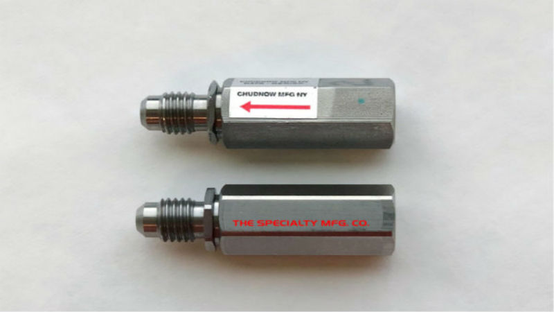
Shuttle valves operate to allow media from two different sources to be supplied through a system without any concerns about cross-contamination or flow of the media between the two inlet ports.
A pneumatic shuttle valve is used on a system where the media is either air or a specific type of gas. Often, particularly with different types of gases, the use of a shuttle valve has been essential for operational safety and to prevent the mixing of different types of gas. In other situations, the use of the shuttle valve allows for two different sources of the same type of gas, or even compressed air, to remain at a constant level of flow to the outlet port and downstream from the valve in the system.
The Design
The design of a pneumatic shuttle valve is similar to a T shape, with all three sections of the T equal in length. The two inlets are on the top of the valve in a straight line, with the middle of the T the outlet port.
Most commonly a ball is contained within the valve. It moves between the two inlet valve ports based on the pressure difference, completely sealing one if the other is open. This allows the flow through the valve outlet to remain constant as the pressure change from the two inlet ports is the mechanism by which the valve functions.
When designing a pneumatic shuttle valve, one of the most important considerations is the type of connection with the three lines. A hose barb connection is ideal for most miniature valves, but a threaded port is also possible and works well with many applications.
The other factor to consider with any type of valve in a system is the seal material. The most common options include Buna, Fluoroeslastomer, or EPDM, and all offer durability and reliability in pneumatic systems.


